AU/NZ Based Calculations
How to Design a Masonry Retaining Wall
The present sheet deals with the analyses and design of masonry retaining wall. The masonry retaining wall is a composite retaining wall constructed u…
How to Design a Masonry Retaining Wall
The present sheet deals with the analyses and design of masonry retaining wall. The masonry retaining wall is a composite retaining wall constructed using the commercially available masonry units and no fines concrete. The permissible height of masonry retaining wall mainly depends on the strength of masonry stone and usually suggested by the stone supplier. The ClearCalcs masonry design calculator includes several available masonry stone details. However, users can input customized masonry details as well. The cross section of a typical masonry retaining wall is shown in the figure below.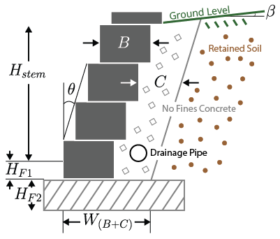
General Notes
The present design calculator provides static design of masonry retaining wall with no shear key. Effects of wind and earthquake loads were not considered. The retained soil is considered in active state and the passive resistance to the base soil in front of retaining wall is ignored. It is recommended to use cement stabilized base pad. The judgment of maximum possible retaining wall height should be based on the type of masonry unit and generally suggested by the masonry unit manufacturer. The dead load at the top of the masonry retaining wall is not consider.Basics of Masonry Retaining Wall Design
In order to satisfy the strength and serviceability criteria the designed masonry retaining wall should be able to resist the sliding and overturning caused by the combination of factored destabilizing loads and moments based on AS 4678:2002. The bearing capacity of foundation soil should be checked under the combined effects of factored vertical and horizontal loads based on AS 4678:2002. Only no fines concrete should be used along with the masonry units along with the drainage pipe to omit the water pressure effects.Input Required from the Users
Users should define the total height of retaining wall stem (above ground level), inclination of retaining wall stem towards the backfill, inclination of backfill and density of no fines concrete.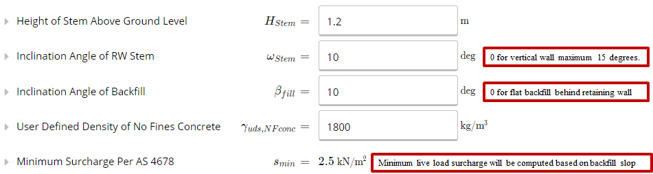 Selection of Retained Soil Properties
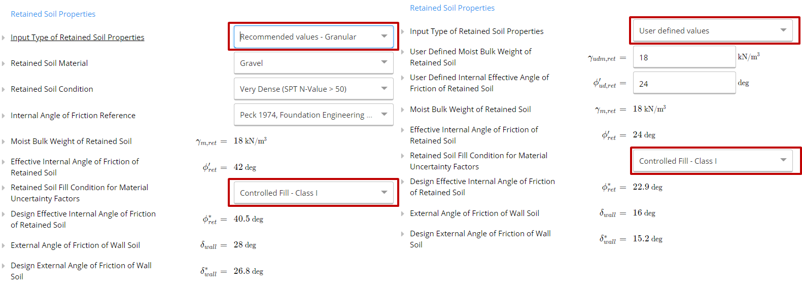
The user could either select the standard retained soil properties based on the available data or could also define the retained soil properties based on the geotechnical report (it is recommended to use a geotechnical interpretative report).
The user needs to select the retained soil condition in order to get the uncertainty factors for the retained soil based on AS 4678:2002.
Based on the uncertainty factors the ClearCalcs calculator will calculate effective angle of internal friction of retained soil and design external angle of friction of wall soil base on AS 4678:2002.
Movement of Masonry RW
During the movement of retaining wall away from retained soil, active state movement mobilized the earth pressure due to which the earth pressure behind the retaining wall reduced.Selection of Base Soil Properties
Similar to the retaining soil modules the base soil properties could be calculated either using the ClearCalcs default values or user could also define the base soil properties based on the geotechnical interpretative report.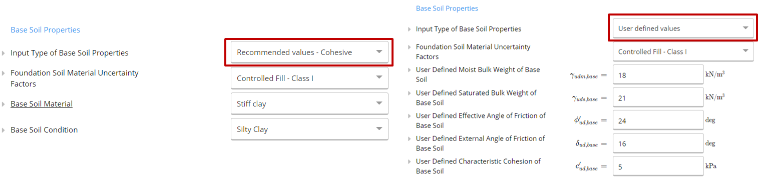
Selection of Masonry Units
The masonry units could be selected based on the ClearClacs masonry unit data base (Industry Supplied Masonry Blocks) or based on the customized Masonry blocks.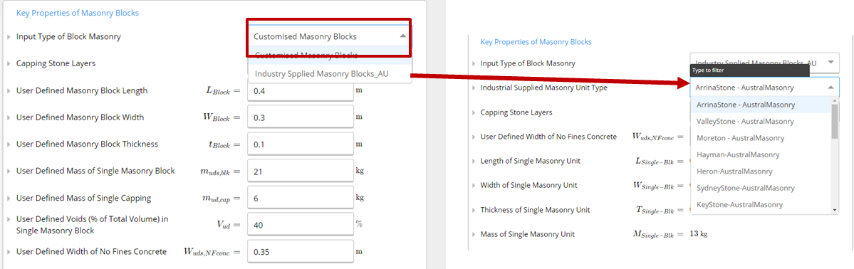
Finding Density of Composite Retaining Wall
Once the details of masonry units are entered the ClearCalcs calculator will calculates the density of composite retaining wall.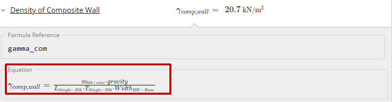
Design for Retaining Wall Sliding and Overturning
- In order to keep the reaction (from foundation base) always below the retaining wall base (width of masonry stone + No Fines Concrete), the minimum distance from retaining wall toe to point of reaction is kept as 1/6 of retaining wall base.
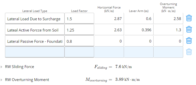
- The load factors for the live load surcharge, horizontal force for soil (stabilizing and destabilizing) and retaining wall dead load (stabilizing) are defied based on AS 4678:2002.
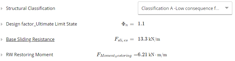
- The structural classification factor based on AS 4678:2002 could be selected from the dropdown list.
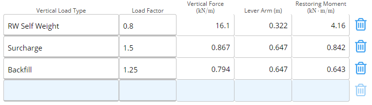
- The ClearCalcs calculator then calculates the factored horizontal load, overturning moment and factored vertical load, stabilizing movement (as shown in the image below) based on which the global stability of masonry retaining wall could be calculated against sliding and overturning.
Design for Bearing Pad
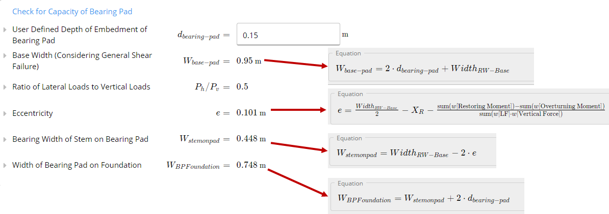
It is recommended to used cement stabilized gravel as base pad, the user can also enter friction angle for base pad. It is recommended to use Control fill-Class I as base pad material. The designed effective angle of internal friction of bearing pad is used for estimation of base sliding resistance.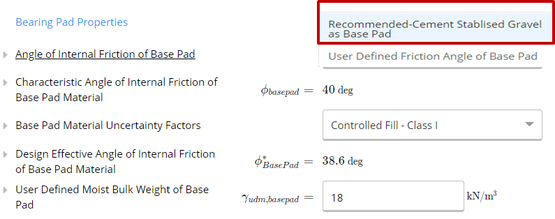 In order to find if the foundation is capable of resisting the factored vertical load, The ClearCalcs template calculates the bearing width of bearing pad on foundation (greater of base width and width of bearing pad on foundation).
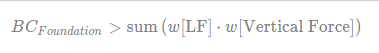
 Once the bearing width of bearing pad on foundation is calculated. Designed ultimate bearing capacity of foundation soil is calculated which should be greater than the factored vertical load on bearing pad.

 References:
1. Das, B. M. (2019). Advanced soil mechanics. CRC Press.
2. AS 4678:2002.
References:
1. Das, B. M. (2019). Advanced soil mechanics. CRC Press.
2. AS 4678:2002.