Free Steel Bolt Group Analysis Calculator
Free and easy to use calculator for the analysis of numerous steel bolts, considering in-plane shear and moment loads.
Start your free ClearCalcs trial to unlock linking to other calculators, saving and export, as well as even more calculators for wood, steel, and concrete beams, columns, and footings.
Get More Functionality with a Free ClearCalcs Trial
Experience the full power of ClearCalcs with a 14 day free trial and start being more productive.
How to Use The Free Steel Bolt Group Analysis Calculator
The ClearCalcs steel bolt group allows the user to analyze numerous steel bolts located at arbitrary X and Y positions in a few simple steps. It considers in-plane shear and moment loads and analyzes symmetrical and unsymmetrical bolt groups using a powerful finite element analysis engine.
Signing up for a ClearCalcs account will unlock further advanced features for design and analysis of steel bolts and a variety of other structural elements.
The sheet is divided into three main sections:
- ‘Key Properties’, where the user inputs each individual bolt location.
- ‘Applied Loads and Eccentricities’, where the user can input the magnitude of in-plane concentrated loads.
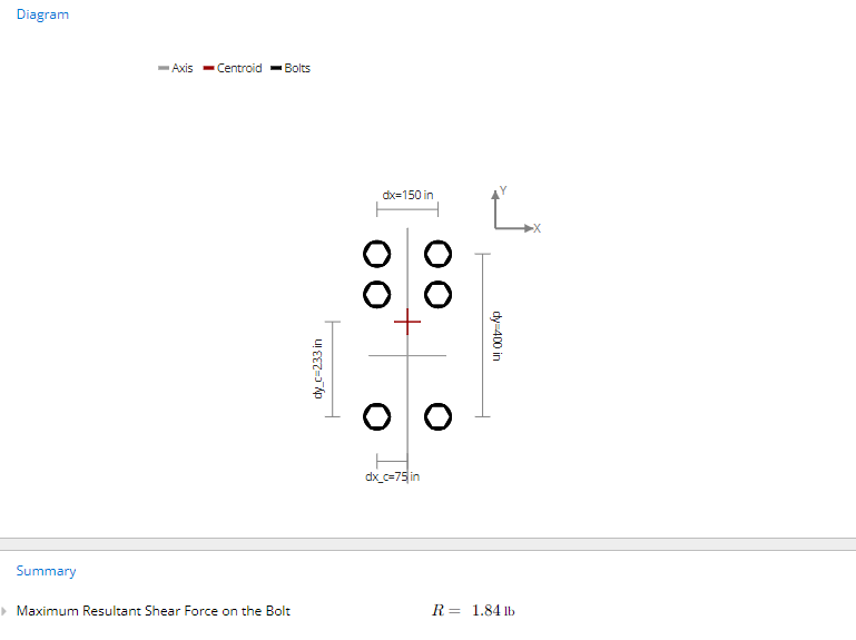
- ‘Summary’, which displays the key outputs of maximum shear on the bolt and diagrams.
A ‘Comments’ section is also included for the user to leave any specific design notes. Clicking on any of the input/property labels gives a descriptive reference explanation.
1. Input Key Properties
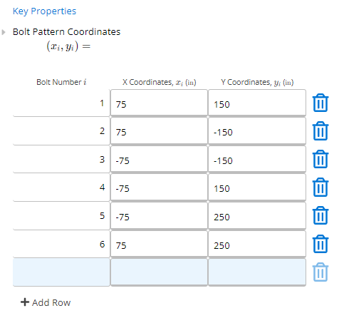
The properties of the steel bolt are specified by typing directly into the Bolt Pattern Coordinates input fields.

Users can enter each individual bolt location in a Cartesian coordinate system.
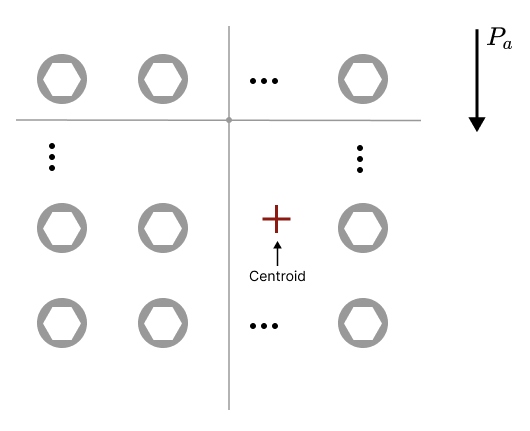
The centroid of the bolt group is automatically recalculated once the user inputs the X and Y coordinates. Therefore, the X and Y axis displayed in the diagram are arbitrary and determined by the user, and they may not necessarily align with the centroid’s position.
2. Input Applied Loads and Eccentricities
Once the user is satisfied with the coordinates of the bolts, the applied vertical load can be input into the calculator.
Applied Vertical Load, Pa: The vertical load that is acting on the bolt group. Note that this load is the factored in-plane shear load.

Next, the user specifies the X coordinates of the applied load, and the calculator will automatically generate the horizontal distance between the applied load and the centroid of the bolt group, or Horizontal Eccentric Distance from Centroid, e.
The resulting calculation will generate the shear loads on the individual bolt farthest from the centroid. The calculation includes:
Direct Vertical Shear Force on the Bolt, Vp: The vertical force on a single bolt due to the applied vertical load Pa. Each bolt is assumed to resist an equal share of the direct shear.
Vertical Shear Force on the Bolt Due to Eccentricity, Ve: This is the vertical shear force acting on the farthest bolt due to eccentricity. Typically the most remote bolt from the centroid experiences the greatest shearing forces compared to the other bolts.
Horizontal Shear Force on the Bolt Due to Eccentricity, He: This is the horizontal shear force acting on the farthest bolt due to eccentricity. Typically the most remote bolt from the centroid experiences the greatest shearing forces compared to the other bolts.
Sum of Vertical Shear Forces on the Bolt, Vt: The sum of all the vertical shear forces on the bolt farthest from the entroid of the bolt group is caused by direct vertical shear and shear due to eccentricity. Note that each bolt is assumed to resist an equal share of the direct vertical shear and a share of the eccentric moment proportional to its distance from the centroid.
Sum of Horizontal Shear Forces on the Bolt, Ht: The sum of all the horizontal shear forces on the bolt farthest from the centroid of the bolt group.
3. Calculation Summary Outputs
Once the bolt location and the applied vertical load have been specified, the calculator automatically uses equations of statics to determine the Maximum Resultant Shear Force on the Bolt, which is the sum of all the maximum horizontal and vertical shear forces on the bolt farthest from the centroid of the bolt group.
